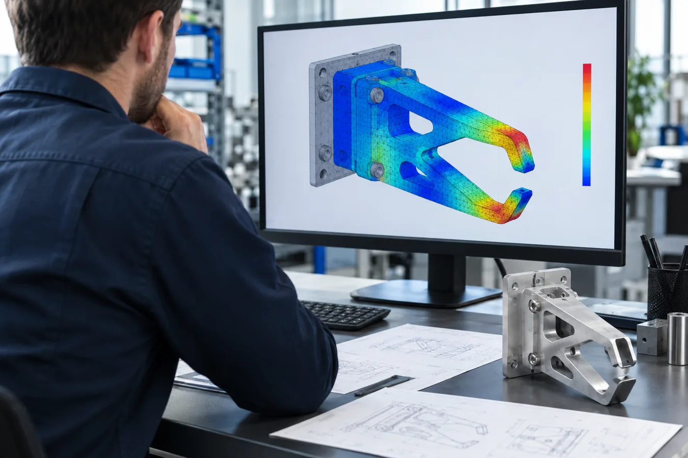
A robot rated for a given payload is not automatically suitable for every tool with a lower mass. A compact tool close to the flange and a long tool carrying the same mass can place very different demands on the wrist.
The load review needs the complete moving assembly, its mass distribution, and the intended motion. Begin before the gripper geometry and robot selection are treated as fixed.
Count everything that moves with the tool
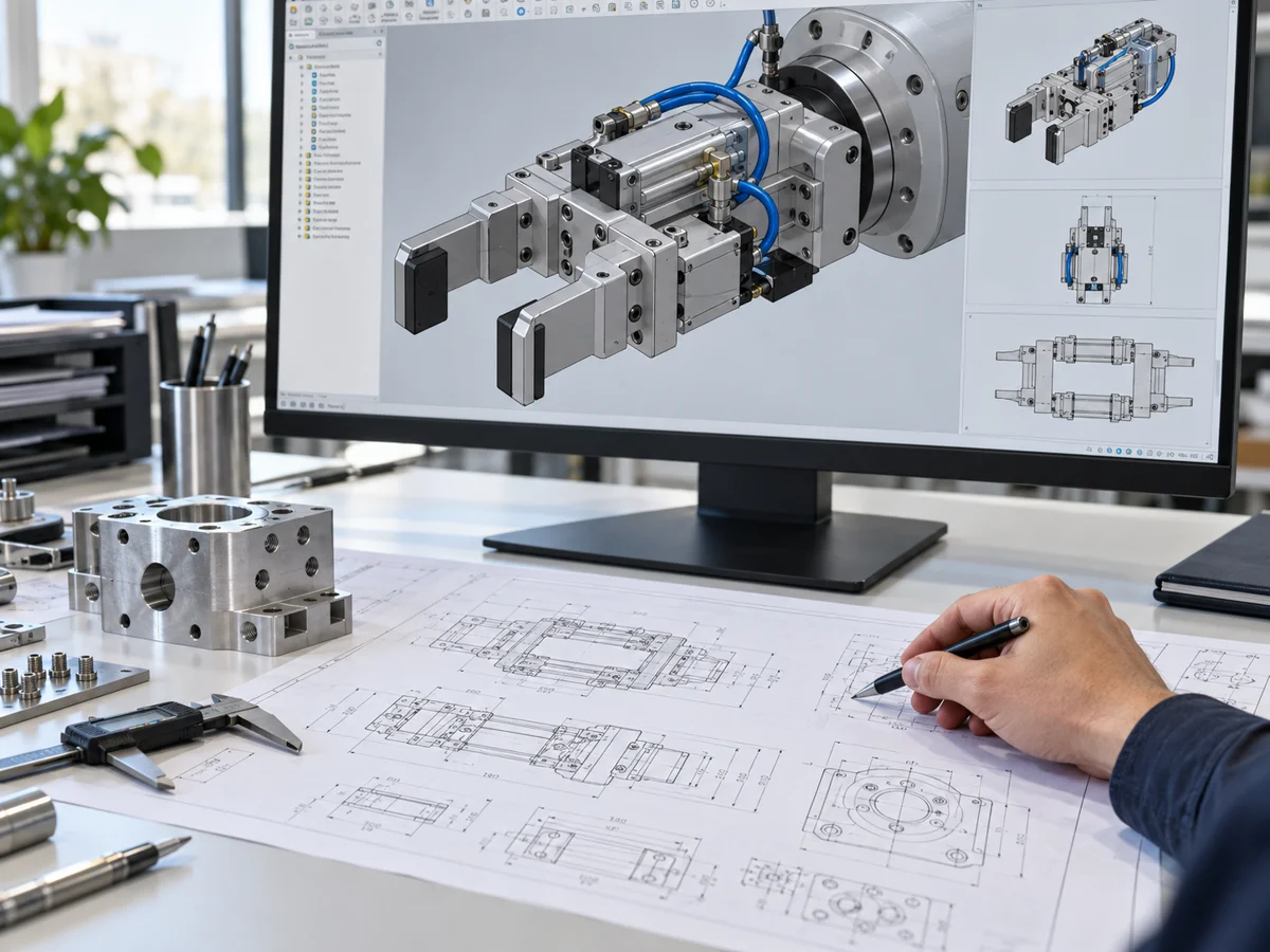
Include the gripper body, fingers, adapter plates, tool changer, sensors, fasteners, carried part, and other relevant attached equipment. Identify any external cable or hose forces that may need separate consideration. Check that CAD materials and densities are assigned rather than accepting the assembly mass at face value.
Use a load-state table when the tool changes during production. Empty, loaded, partially loaded, and alternative product configurations may have different centers of gravity. The heaviest configuration is important, but it is not necessarily the only limiting one.
Use the correct reference frame
Center of gravity is a location, not just a distance. Report its coordinates with a clearly defined origin and axes. Inertia also needs a reference point, axis orientation, and units. A technically correct CAD export can be unusable if the receiving robot software expects a different convention.
For example, Universal Robots documents payload mass, center of gravity, and inertia as distinct settings, with its inertia matrix referenced to the payload center of gravity and axes aligned with the tool flange. That is a specific manufacturer convention; use the instructions for the selected robot and controller. See Universal Robots’ payload documentation.
A simple example shows why reach matters
For illustration only, consider a 10 kg mass whose center of gravity is 0.10 m from a horizontal reference axis. Gravity produces approximately 9.8 N·m of moment about that axis. Moving the same mass to 0.30 m increases that moment to approximately 29.4 N·m. The calculation uses mass × gravitational acceleration × perpendicular offset.
This is not a robot-sizing calculation. It leaves out the rest of the tool, motion, other axes, and manufacturer-specific limits. It shows why “we are under the kilogram rating” is an incomplete check.
Rotational inertia describes resistance to angular acceleration and depends on how mass is distributed. Removing mass near the center and adding it farther away can change wrist demands even if total mass stays similar.
Review load states against the intended application
| Data | Review question |
|---|---|
| Robot and controller | Which exact model, mounting, and applicable load limits govern? |
| Tool CAD and materials | Does the model include the complete moving assembly? |
| Part configurations | Which empty, loaded, and asymmetric states are possible? |
| Mass properties | Are center of gravity, inertia, units, and axes documented? |
| Motion and process | What paths, orientations, timing targets, and process forces are intended? |
Review the manufacturer’s applicable load diagrams, wrist moment and inertia limits, and analysis tools where available. Reach, collisions, cable routing, and process forces are related checks, but they should not disappear inside a single “payload approved” statement.
Keep the study connected to the released tool
A longer finger, a replacement tool changer, or a new product can change the result after the original study. Record the tooling revision and the load states analyzed, then identify changes that require re-evaluation.
The study deliverable should state the inputs, manufacturer references, conditions evaluated, unresolved data, and any limits on the conclusion. Physical setup and commissioning still have to verify the actual installation and the controller configuration. If the analysis drives a new robot choice or a tooling redesign, retain the alternatives and the reason for the decision with the project records.