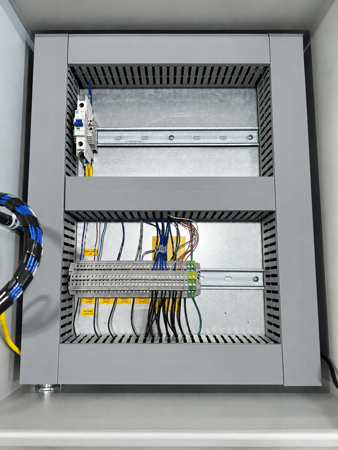

A schematic can explain how a circuit works while leaving the panel builder and installation team without information they need. Where does the cable enter? Which terminal accepts the field connection? Which part number is approved? Which PLC tag corresponds to the device?
Define the electrical package by the decisions it must support. For an industrial automation project, the following six deliverables provide a useful starting structure. Their depth depends on whether the assignment ends at design or continues through build and commissioning.
1. Design basis and power distribution
Record incoming supply information, connected loads, operating environment, required labeling, and customer standards. Identify unresolved site inputs and the person responsible for them. The design basis should be short enough to use during reviews, with references to the detailed calculations and specifications where needed.
The power-distribution drawings then describe the selected circuits and their relationships. Component sizing and protection require the applicable design methods and qualified review; a drawing should not hide missing calculations behind a part number.
2. Schematics and device identification
Agree on drawing format, symbols, cross-references, device tags, and wire identification. The important test is traceability: can a reviewer follow a field device through its terminals, circuit, I/O point, and software reference?
For an illustrative clamp station, the clamp-closed sensor should have a consistent identity in the mechanical layout, electrical schematic, I/O list, PLC project, and HMI diagnostic text. If each discipline uses a different name, create a mapping before release. Do not leave the commissioning team to infer it at the machine.
3. Panel layout and installation interfaces
Define component placement, enclosure dimensions, door devices, cable entry, terminal locations, and access requirements. Include the information needed for mounting and routing decisions. Panel layout is not simply a scaled bill of materials: thermal constraints, manufacturer clearances, segregation, and service access can change the arrangement.
Siemens’ control-circuit planning guidance connects supply planning and project documentation. For a specific project, retain the selected manufacturers’ installation instructions with the design references.
4. A bill of materials that can be purchased
Require manufacturer, full part number, quantity, and the drawing reference where the component is used. Describe what is included in an assembly and what must be ordered separately. Accessories, connectors, mounting parts, and licenses can otherwise fall between engineering and purchasing.
Use an approved-alternate column only when alternatives have actually been reviewed. A note saying “or equivalent” transfers a technical decision without defining who owns it. When a substitution is accepted, update both the BOM and affected drawings under the same revision process.
5. I/O, networks, and field connections
The I/O schedule should connect the device description, signal type, location, electrical reference, and controls address or tag. The network information should identify device roles, interfaces, and the owner of addressing and configuration. Keep credentials out of ordinary drawing packages.
| Interface | Question to close |
|---|---|
| Panel to field device | Who selects, supplies, installs, and verifies the cable? |
| PLC to robot or process equipment | Who defines the handshake, timeout, and fault response? |
| Machine to plant network | Who approves the connection and configuration? |
| Design to commissioning | Who records and approves site changes? |
6. A controlled handoff
Specify native files, PDFs, revision records, and the status of each deliverable. Distinguish “approved for construction” from the final package updated after installation. Decide whether the scope includes incorporating field changes and when that work ends.
Close the package with an interface review involving mechanical, electrical, controls, and the receiving team. A missing mounting dimension or an ambiguous device tag is cheaper to resolve while it is still a document issue. For panel quotation, list these deliverables separately so design responsibility remains visible.